Filter By

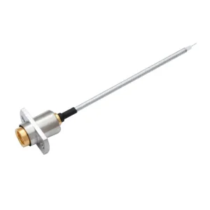
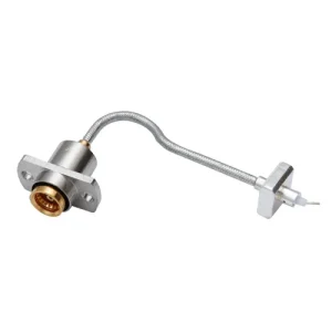
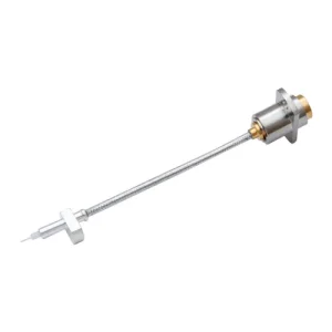
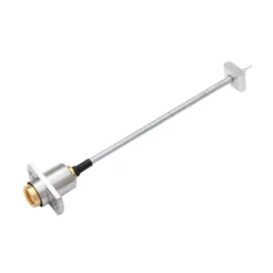
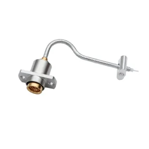
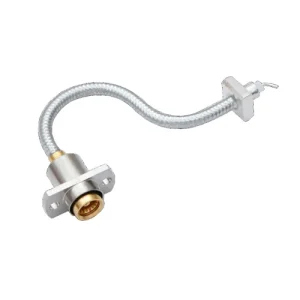
BMA cable assemblies are high-performance RF coaxial connectors designed for reliable signal transmission in demanding applications. Known for their compact size, durability, and secure bayonet coupling, BMA connectors are widely used in telecommunications, aerospace, and military systems. Our premium BMA cable assemblies ensure superior connectivity, low loss, and exceptional performance.

Base Products

BMA .086" 74

BMA .086" 74

BMA,.086",50Ω,Brass/Gold,74mm

BMA .086" DZ 75

BMA .086" DZ 75

BMA-DZ,.086",50Ω,Brass/Gold,75mm

BMA .086" DZ 66.5

BMA .086" DZ 66.5

BMA-DZ,.086",50Ω,Brass/Gold,66.5mm

BMA .086" DZ 86

BMA .086" DZ 86

BMA-DZ,.086",50Ω,Brass/Gold,86mm

BMA .086" DZ 69

BMA .086" DZ 69

BMA-DZ,.086",50Ω,Brass/Gold,69mm

BMA .141 DZ 94mm

BMA .141 DZ 94mm

BMA-DZ,.141,50Ω,Brass/Gold,94mm

Category Insights

BMA connectors combine a push‑on bayonet mechanism with a miniature form factor, allowing fast blind‑mate connections without the threaded coupling found on SMA or N‑type parts. This design reduces mating time in densely packed modules, eliminates torque‑wrench requirements, and maintains a repeatable 50 Ω interface up to 18 GHz. The result is lower VSWR, consistent phase integrity, and reliable performance in environments where space, weight, and speed of assembly are critical.
You will find BMA assemblies in phased‑array radars, airborne telemetry links, satellite payloads, secure military radios, and 5G millimeter‑wave test fixtures. Engineers choose them because the blind‑mate bayonet tolerates misalignment during quick equipment swaps, the compact housing fits tight RF line‑replaceable units, and the rugged construction withstands vibration, temperature cycling, and high‑G shock. These characteristics make BMA the connector of choice whenever mission‑critical uptime and rapid maintenance matter.
Start by matching your frequency band—our assemblies are qualified from DC to 18 GHz, with low‑loss variants extending to 26.5 GHz. Next, confirm the required impedance (always 50 Ω for BMA) and choose a cable type that balances insertion loss against flexibility, such as RG‑405 for tight bends or low‑density PTFE dielectric for extreme phase stability. Finally, specify environmental ratings (IP‑seal, vibration, temperature) and plating options like passivated stainless or gold to meet corrosion or outgassing requirements.
Handle all blind‑mate connections with gentle axial pressure—never twist the bayonet interface. Keep coupling surfaces clean with lint‑free swabs and isopropyl alcohol, inspecting regularly for debris that can raise contact resistance. Route cables with generous bend radii (≥ five times the diameter) and secure them with strain‑relief clamps to minimize flex during vibration. Periodic visual checks for pin recession, housing damage, or dielectric discoloration help detect wear before it degrades signal integrity.
Our standard series delivers ≤0.05 dB insertion loss per connector at 10 GHz and VSWR ≤1.15:1 through 18 GHz, while the low‑loss line tightens that to ≤0.03 dB and VSWR ≤1.10:1. Shielding effectiveness exceeds 90 dB, maintaining EMI immunity even in crowded racks. Stainless‑steel bodies endure 500 mating cycles, 1,000‑hour salt‑spray, and −55 °C to +165 °C operation, ensuring consistent amplitude, phase, and PIM performance across your system’s full thermal and mechanical envelope.