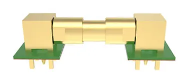
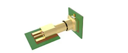
Our board-to-board connector portfolio offers engineered solutions for diverse RF challenges across frequency ranges, power requirements, and physical constraints. Each interface combines proprietary design elements with proven RF principles.


| Parameters | High-Frequency | High-Power | |||||
|---|---|---|---|---|---|---|---|
| SMPM | SMP | P-SMP | AFI | HD-AFI | HD-EFI | UD-AFI | |
| Impedance | 50 Ohm | 50 Ohm | 50 Ohm | 50 Ohm | 75 Ohm | 75 Ohm | 50 Ohm | 50 Ohm |
| Max Frequency | 65 GHz | 40 GHz | 10 GHz | 6 | 3 GHz | 18 GHz | 6 GHz | 6 GHz |
| Min PCB Spacing | 6.6 mm | 9.1 mm | 12.6 mm | 12.7 mm | 11.5 mm | 11.5 mm | 8 mm |
| Power Handling | 50 W @ 2.2 GHz @ 25˚ C | 30 W @ 2.2 GHz @ 25˚ C | 200 W @ 2.2 GHz | 200 W @ 2.2 GHz @ 8.8˚ C | 10 W @ 2 GHz @ 25˚ C | 40 W @ 2.2 GHz @ 85˚ C | |
| Axial Misalignment | 0.25 mm | 0.25 mm | 2.00 mm | 1.00 mm | 2.00 mm | 1.40 mm | 1.00 mm |
| Radial Misalignment | 0.51 mm | 0.51 mm | 1.32 mm | 0.80 mm | 0.80 mm | 0.7 mm | Depends on bullet length (4.8° tilt) |
A system's ability to maintain consistent RF performance while compensating for mechanical misalignment between PCBs
Maximum permissible vertical displacement between mated boards while maintaining specified performance
Mating retention styles: Limited (medium), Full (fixed), or Smooth Bore (sliding) for different assembly needs
Design feature allowing connectors to mate without visual alignment, requiring generous tolerance compensation
Our RF engineers can recommend the optimal solution for your specific frequency, power, and mechanical requirements.